MikroTik Optimal Wireless Config for Transparent Point to Point or Backhaul

I am often asked what is the optimal configuration for a point to point with Mikrotik, typically SXT’s.  I would stress that the fewer settings you make, the better the link will work so I don’t recommend tweaking, just set the basics.  Here are screen shots of everything that needs to be set to make a high capacity point to point.  The red boxes are settings that are peculiar to that end of the link and the blue boxes are the settings that must match both ends of the link:

Wireless AP End of Link (also called bridge mode on a point to point)

Station End

ISP Supplies is a premiere MikroTik stocking distributor in the USA and we pride ourselves on offering more than boxes; we also offer knowledge.  Our team is knowledgeable, willing and able to provide technical assistance with any MikroTik device.


The post MikroTik Optimal Wireless Config for Transparent Point to Point or Backhaul appeared first on Steve Discher.


Source: Blog

Getting Started With Baicells LTE

Baicells has created a new “LTE How To” for new WISP operators.  As you may already know, Baicells equipment is Plug & Play and by far the easiest LTE devices to set up and add to your current network. Many common startup problems evolve from the operator making too many changes during startup. Keep it simple to start with and tweak settings after the system is live.

The new guide can be found HERE.

One thing you will notice in the guide is that the simplicity of the product is enhanced by the fact that UE’s (CPE devices) and eNodeB’s (Base Stations) must be associated with the new owner’s CloudCore account to operate.   ISP Supplies is the only distributor that automates that process through our custom application, SIMPro. SIMPro allows us to scan the serial numbers of eNodeB’s and the IMSI’s of UE Sim Cards into our database, tie them to your SIMPro account and automatically email them to Baicells for provisioning.  You can even add notes to the devices in the SimPro app.  When your product arrives, it is ready to deploy.

Baicells LTE SimPro

LTE is the future of fixed wireless and you can learn more on my blog.

ISP Supplies is one of the largest Baicells LTE distributors in North America with hundreds of successful LTE deployments.  Our knowledgeable sales engineers are standing by to assist you in designing and deploying LTE in your existing or startup network.  For access to SimPro or to discuss fixed LTE, call us today at 855-947-7776.

The post Getting Started With Baicells LTE appeared first on Steve Discher.


Source: Blog

MikroTik Automatic Failover Two Gateways

There’s a million ways to do this on the wiki and the web but none of them fit my particular application.  Let me explain:

1.  The weak point in my network was an AirFiber 24 upstream from the tower I am connected to wirelessly.  This is the link that goes down in heavy rain causing an outage at our office to PROVIDER1.  We have a backup connection through a second provider that is slower but being 5GHz doesn’t drop in the rain, PROVIDER2.

The network is like this:

[MikroTik CCR1036-12G-4S]
—[RBSXT]—[RBOmniTikU-5HnD[—[AF24]—[PROVIDER1]
—[RBSXT]—[PROVIDER2]

2. Simple floating static routes with check gateway doesn’t help because on PROVIDER1 we never drop our 5GHz connection to the tower, it’s the upstream link that fails.

3. I tried recursive routes and it works but the failover was still lacking and seemed sporadic at best.

4. When failover did occur, the VOIP PBX would hold the connection open through the dead provider and some phones in the office wouldn’t work at all, rebooting the phone was the only solution. We tried a ton of solutions and never got it to work consistently.

The solution that works the best is as follows.  I am using a combination of static routes, firewall rules and Netwatch scripts. Here it is:

The Netwatch script watches 4.2.2.4 (a public DNS server). If it goes down:

  • It changes the distance on the default router to PROVIDER1 to 20 making it inactive.  Now all traffic defaults through PROVIDER2.
  • It emails me that the gateway has changed. Please not you must set up your email server IP, and any authentication in /tools e-mail first.
  • It clears any connections to my VOIP gateway, thereby causing them to re-establish, interestingly calls do not drop!
  • When pings return, it sets the distance on the default route through PROVIDER2 back to 1 making it the active route and then clears all connections to the VOIP gateway again.
/tool netwatch
add comment=CheckCon down-script="/ip route set [find comment=\"\
    PROVIDER1\"] distance=20\r\
    \n/ip route set [find comment=\"PROVIDER2\"] disabled=no\r\
    \n/tool e-mail send to=\"YourEmailAddress\" body=\
    \"Connection with PROVIDER1 Lost, Switched to PROVIDER2\" \
    subject=\
    \"Lost connection with PROVIDER1\"\r\
    \n/ ip firewall connection remove [find dst-address=\"\
    YourVoipGatewayIP\"]" host=4.2.2.4 interval=5s timeout=2s \
    up-script="/ip route set [find comment=\"PROVIDER1\"] distan\
    ce=1\r\
    \n/ip route set [find comment=\"PROVIDER2\"] disabled=no\r\
    \n/tool e-mail send to=\"YourEmailAddress\" body=\
    \"Connection with PROVIDER1 Regained, Switched back to PROV\
    IDER1\" subject=\"Regained connection with PROVIDER1\"\r\
    \n/ip firewall connection remove [find dst-address=\"\
    YourVOIPGatewayIP\"]"

Next we need to ensure we can only ping our test host through the PROVIDER1 connection.  This is done with a static route through PROVIDER1:

/ip route add 
comment="Force test pings through PROVIDER1" dst-address=4.2.2.4 /
gateway=199.21.228.153

Next we need to comment our default routes.

/ip route
add comment=PROVIDER1 distance=1 gateway=199.21.228.137 scope=\
    11
add comment=PROVIDER2 distance=10 gateway=209.112.225.65

Next we need to ensure that no pings to our test ip go through PROVIDER1 only:

/ip firewall filter add chain=output comment=/
"Drop pings to 4.2.2.4 if they go through PROVIDER2" \
dst-address=4.2.2.4out-interface=ether2 action=drop

As I write this it is pouring rain outside and I have observed it go down 3-4 times and even with people on the phone, calls continue and we haven’t lost the network. I am loving this!

What can I do if my wireless devices don’t roam between my wireless AP’s?

Good question, one I was also asking myself when I set up a large Mikrotik CAPsMAN network. A moving laptop would hang onto a -85 signal when a -70 was available.  It did not make sense.  So, after some research I found some ideas to help you.

When you are walking between access points (assuming they have the same wireless SSID name and same security), you may find that your wireless client, that is your laptop like a mobile phone is still sticking to the distant device and will not roam to the nearest device.

How roaming works:

Roaming is purely a client decision. The wireless client is responsible for deciding it needs to roam, and then detecting, evaluating, and roaming to an alternative AP. WLAN standards bodies (such as IEEE) and industry bodies (such as Wi-Fi Alliance) do not specify when a client should roam, or how the client roams.

So, roaming or not roaming, it is totally decided by your wireless client’s roaming algorithm. Different wireless client vendors’ roaming algorithms are also different and are not generally published.

Resolution:

There is no role played by AP in this client roaming process. So, your best option is to configure your wireless client to achieve fast roaming for you.  Some NIC vendors give some mechanism to control this roaming behavior, specifically Intel.

PC Users

In Intel, it is known as roaming aggressiveness and this setting allows you to define how aggressively your Wi-Fi client roams to improve wireless connection.

Here are the configuration methods on Intel WNIC:

You can go to control panel -> network and internet -> network connection and choose the wireless connection. Right click the wireless connection and choose properties. Click configure and choose Advanced and choose roaming aggressiveness.  Typically there are 5 options. Here are the explanations of these five options:

Lowest: Your wireless client will not roam. Only significant link quality degradation causes it to roam to another access point.

  • Medium-Low/Medium-High: Allow Roaming.
  • Medium: Balanced setting between not roaming and performance.
  • Highest: Your Wi-Fi client continuously tracks the link quality. If any degradation occurs, it tries to find and roam to a better access point.

Mac Users

It is still possible on the Mac, just not as elegant.  Open a terminal window and type the following command all on one line then Enter.  You will need the administrator password of course since this has to run as the root user:

sudo /System/Library/PrivateFrameworks/Apple80211.framework/Versions/A/Resources/airport prefs joinMode=Strongest

This should get your device to drop a weak AP when a stronger signal is available. This will work with any AP setup, Ubiquiti, MikroTik, etc.  Happy roaming!

“WISPatizing” LTE

This is a letter from Patrick Leary at Telrad, I thought worth sharing.

We all know LTE has first been created for the needs of giant mobile operators first. That means the LTE enhanced packet core (called the EPC in LTE-speak) includes a host of features fixed operators may NEVER need, like translating diverse 3G backends into a standardized LTE core. Who wants to pay for that? Not me and certainly not you. As well, being mobile centric first, LTE out of the box EXCLUDES certain things fixed operators like and use, such as Layer 2 services.

Being the first and so far ONLY company out there in the LTE space mainly focused on the fixed space, Telrad is the tip of the spear trying to innovate and idealize the solution for WISPs and other local and regional fixed-focused operators. It has been a struggle. EPC are things that can run deep into 6 figures and we had to find a way for the economics to make sense for your models.

Complicating this, because we use an SDR platform, Telrad is able to do something no other vendor on the planet has done: offer the EPC as a hardware-less, software feature EMBEDDED into each base station as an option. That’s super cool, meaning smaller operators won’t need to shell out for a full centralized EPC. But, that also means we’ve made our lives more difficult because options are another SKU to manage.

We now think we’ve got it as refined as possible and here’s the key to what we’ve done:

Dividing up the EPC functionality to allow for operators to purchase ONLY the features you need, and allowing that granularity to be applied to EITHER the embedded or the centralized EPC models.

So what’s been made granular (and priced much smaller per function)? These are things that in the traditional LTE world are often found as individual appliances. Our centralized core can include them all in one appliance for 1/10th or less of what traditional EPCs can cost. Now we’ve even made it MUCH more affordable than even that, by taking the subsets of EPC functionality and providing them as distinct SOFT modules that can be purchased ala carte into either the embedded or centralized Telrad EPCs. Here are examples:

– Don’t want AAA or need Radius? Fine. We now have a feature called iHSS, which allows MAC level authentication.

– Want to use your Radius, but NOT use our implementation? Don’t get iHSS. Instead get the IWK module, which enables internetworking with an external Radius AAA server.

– Planning ONLY to do best effort or apply a single policy across all subscribers? Fine, no need to have the PCRF functionality of an EPC.

– Want to implement distinct and varied service flows and other QoS services? We’ll offer iPCRF as a module.

These are examples. If you used all the functionality, it would still not cost you any more than how things were first initially priced, even if purchased in pieces, so there is no nickel and diming. The difference is, if you need LESS, you’ll be investing less.

Those of you with firm LTE quotes on the table? We’ll need to revisit them, as the numbers will drop. Those with only estimates at this point? That’s worst case and we’ll get you revisions as you get nearer to pulling the trigger.

One last thing….and it is another big one. With LTE comes the entirely new NMS. Better, lighter, simpler, less cost. I’ll be doing another mail on that as soon as I can.


Java Home Directory Fail Issue on Ubuntu – RESOLVED

Java Home Directory Fail Issue on Ubuntu – RESOLVED

For those of you who’re building your Ubuntu from scratch or even if you did like me and install UniFi on an AirVision NVR, , you might or might not get this after installing UniFi Controller

*Setting Java Home….fail

If that do happen, this might be because since the new Ubuntu, the name of the Java homedir changed according to the CPU architecture used and UniFi is using a hard-coded variable for the Java path in its startup script for some reason. You should change the homedir by editing the init script. (We won’t get into much detail about what is init)

1. Open the init script
sudo nano /etc/init.d/unifi

2. Scroll down with your arrow key, look for a variable called
JAVA_HOME=/usr/lib/jvm/java-6-openjdk

3. Add your instance architecture type after that string.
For example, I’m using amd64bit in my instance, the string should become
JAVA_HOME=/usr/lib/jvm/java-6-openjdk-amd64
DO NOT touch anything else.

4. After the edit just enter Ctrl-X and it will ask you wheter it should save or discard the change. We of course want to save it. Press Y, and press ENTER to save it with the same file name. The nano editor will close

5. Do this string to restart our UniFi Controller.
sudo service unifi restart

6. You suceed when you see
* Starting Ubiquiti UniFi Controller unifi [ OK ]

DHCP Option 43 on MikroTik RouterOS With Ruckus

This one nearly made me tear my hair out. Option 43 is a vendor specific option that many vendors use to tell their devices the IP address of a server they need to access. Ubiquiti UniFi uses it and so does in this case Ruckus. I tried setting the value using a hex generator to no avail and after an email through a friend from a Ruckus engineer, we now have a tool!

Try THIS link to access the tool. I have not yet confirmed it works with Ubquiti UniFi but will try it next. It has the proper syntax for the raw option and Cisco as well.  I think it likely will. Enjoy!

EdgeMAX – VLAN Walkthrough with EdgeSwitch

Obviously there are more detailed instructions on the Ubiquiti site but I just needed a trunk port and a few access ports on my Ubiquiti EdgeSwitch so this is a much for my own documentation as it is for you my valuable customers!

  1. Connect the Admin Computer to a switch port, then navigate to 192.168.1.2 in your web browser.
  2. Note: Make sure that PoE is disabled on this port prior to connecting your device.
  3. Under Switching > VLAN > Status, click Add the vlan to the the EdgeSwitch.  You can also add several vlans at once using a range like this:

original


4. Assuming I want port 1 to be a trunk port, while still under Switching > VLAN > Port Configuration, select 2 from the dropdown menu for VLAN ID.

original-3

5. Then select Ports 0/1 (the trunk port) and apply the following configuration:

original-2


6. Then select Port 0/23 (the access port for UVC belonging to  VLAN2) and apply the following configuration:

original-4

7. Next, navigate to Switching > VLAN > Port Summary, select All from the Display rows dropdown menu. Then select Port 0/23, click Edit, then apply the following configuration:

original-5

8. Finally, click the Save Configuration button at the top-right of the screen to apply the active configuration to the boot configuration, then follow the prompts that appear.

 original-6original-7 original-8That’s it!

MikroTik Wireless CAPsMAN Howto

I was intrigued by the recently new feature being developed by MikroTik called “CAPsMan”.  From the wiki “Controlled Access Point system Manager (CAPsMAN) allows centralization of wireless network management and if necessary, data processing. When using the CAPsMAN feature, the network will consist of a number of ‘Controlled Access Points’ (CAP) that provide wireless connectivity and a ‘system Manager’ (CAPsMAN) that manages the configuration of the APs, it also takes care of client authentication and optionally, data forwarding.  When a CAP is controlled by CAPsMAN it only requires the minimum configuration required to allow it to establish connection with CAPsMAN. Functions that were conventionally executed by an AP (like access control, client authentication) are now executed by CAPsMAN. The CAP device now only has to provide the wireless link layer encryption/decryption.”

When I initially read that, I immediately thought of UniFi, Ubiquiti’s centrally managed enterprise wireless platform.  From that point forward, I spent little time learning the facts and immediately began comparing the product to UniFi only to find I was disappointed with CAPsMAN and why wouldn’t I be?  It had no web interface, no fancy graphs and seemed difficult to configure.  I was wrong.  I am not saying there is eye candy, because there isn’t but it’s beauty is in it’s innovation, and function over form.  Best of all it can be built using existing, already deployed hardware, thereby using software to redefine your wireless network.

In summary, the CAPsMAN concept involves using your existing internet router (must be a MikroTik of course) and adding the optional CAPsMAN package.  Then installing theCAPsMAN package on the AP devices.  Conventional AP’s become CAPs and the router serves as the CAPsMAN controller and you are off to the races.  Each CAP becomes simply an interface on the router.  An interface you can bridge, address, route, whatever, treat it like any other interface.  Want to know who is associated with a certain AP?  Check the main CAPsMAN registration page.  There is one page that summarizes all CAPs!  Want to add a secondary or third ( I don’t like the word tertiary) , easy, just add it in CAPsMAN and it pushes the config to all the CAPs.  Same thing with adding a new WPA key, click once, type, click ok and done, all CAPs get configured automatically.

Hopefully I have wet your appetite enough for you to dive in and try it so here is a step by step to get you going.   Everything else is a modification of this basic setup.

CAPsMan HowTo

First, you must install thee CAPsMAN wireless package on the router and all AP’s.  If using CAPs, this is already done for you.  However, must CAPs come with CAPsMAN version 1 and you want version 2 so download it from MikroTIk.com, drag the file to your files window and reboot all devices.

CAPsMAN Router

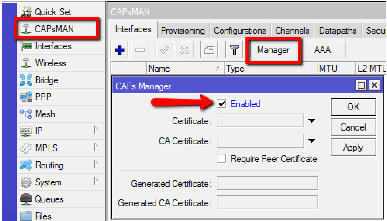
Once the router has the CAPsMAN package, open Winbox and enable the CAPsMAN manager service.

CAPsMAN Server1

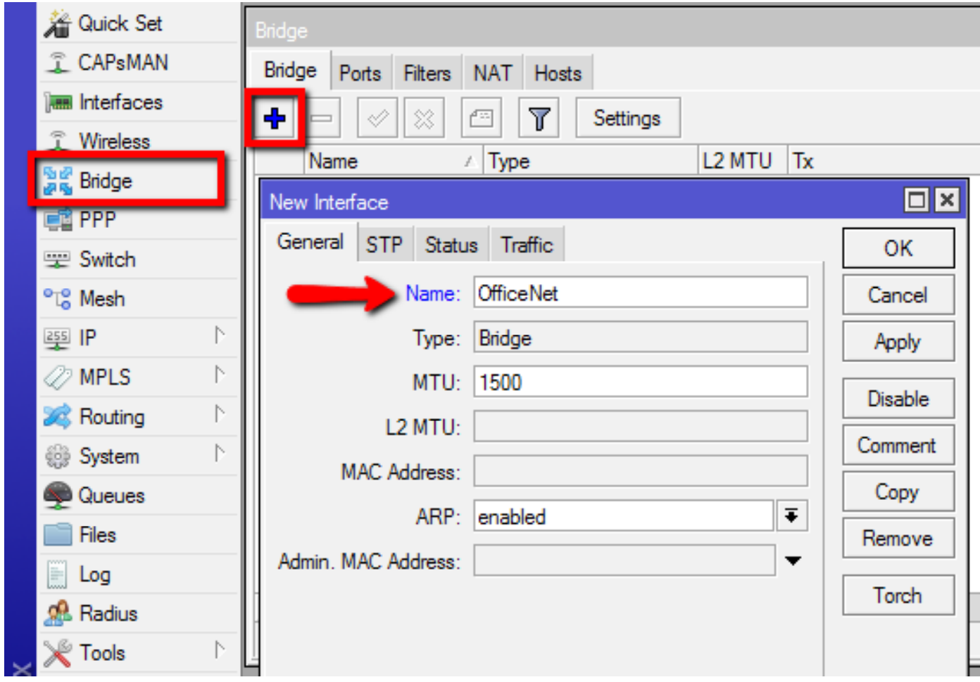
Next create a bridge interface for the CAPs to be added to dynamically when they appear on the network.

CAPsMAN Server2

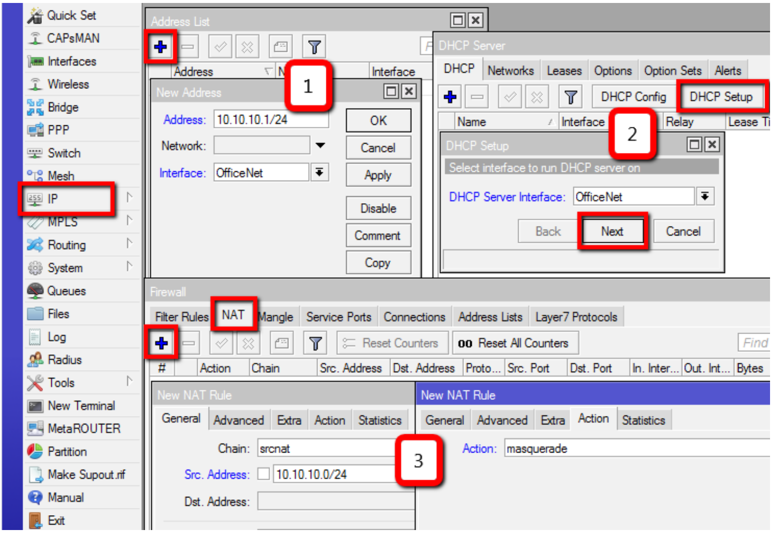
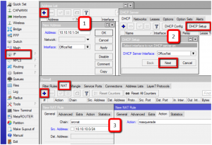
Add an IP address, DHCP Server and a NAT rule.  You can learn how to do this elsewhere, like wiki.mikrotik.com for example.

CAPsMAN Server 3

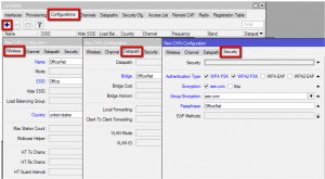
Add a new CAPsMAN configuration.

CAPsMAN Server 4

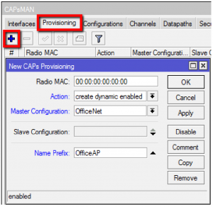
Add a new provisioning rule.

CAPsMAN Server 5

Configuring the CAP

This is a sticky wicket because there are a few options.

Option 1. Using a RouterBoard MAP or CAP

These are purpose built devices and I really like them for new installs.  There is one  design issue I have and that is they have a default config that is suited for a stand alone configuration.  Basically it is a wireless AP with DHCP server on the wlan, DHCP client on the Ethernet, etc.  I would rather it came factory configured to be a CAP.  Clearly then did not consult me.  To turn it into a CAP, there is a hardware option I will cover here.

Note that most CAPs and MAPs come with version 1 of the CAPsMAN software so BEFORE you use the hardware switch to set them to CAP mode, upgrade the CAPsMAN package!

CAP

There is a reset switch located on the underside of the device next to the Ether jack.  Hold it down and apply power via the supplied POE adapter.  Hold it steady for 10 seconds.  The wireless LED will go from flashing to solid.  Then release and it will load the CAP config and look for a controller on the local LAN.  The is a Layer 3 discovery option for when the CAPsMAN is on a different Layer 3 segment or out on the internet somewhere but that  is covered in the wiki as well.

Note: What I have described here is NOT covered correctly in the instruction sheet that comes with the CAP so throw that away and follow my instructions to save a lot of headache.

Within 2-3 minutes the CAP will be in CAP mode.

MAP

There is a reset switch located on the side of the device.  Hold it down and apply power via the supplied POE adapter.  Hold it steady for 10 seconds.  The AP/CAP LED will go from solid to flashing, exactly the opposite of the CAP’s LED behavior.  Standardize guys!  Then release and it will load the CAP config and look for a controller on the local LAN.

Note Again: What I have described here is NOT covered correctly in the instruction sheet that comes with the MAP so throw that away and follow my instructions to save a lot of headache.  Again.

Within 2-3 minutes the MAP will be in CAP mode.

In either case, forget the LEDs and hold the switch exactly 10 seconds and you are good to go..  When you release the switch the LEDs should do a quick blip, 2-3 of them will do it simultaneously telling you it is applying the config.  You will learn to recognize that.  Or not.

Option 2. Converting Non-CAPs or MAPs to CAPs

Simply download the version 2 CAPsMAN and drag it to the files window.  Reboot and then configure the AP by first removing any existing configuration.  Then configure it to be a CAP by using the following script which you can copy and paste to a terminal window:

/interface wireless
set [ find default-name=wlan1 ] l2mtu=1600 ssid=MikroTik
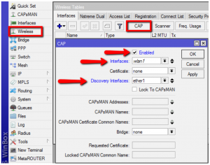
/interface wireless cap
set discovery-interfaces=ether1 interfaces=wlan1 enabled=yes
/ip dhcp-client
add default-route-distance=0 dhcp-options=hostname,clientid disabled=no interface=ether1

The device will then communicate with the CAPsMAN and become a CAP.

CAPsMAN Server 6


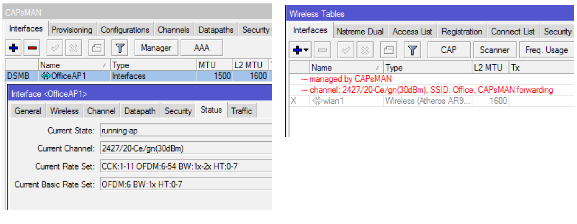
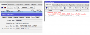
Once the CAP is configured, the CAPsMAN will show it’s status and the CAP will tell you it is being managed by the CAPsMAN;

CAPsMAN Server 7

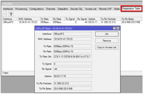
The registration table will then contain registrations for all CAPs:

CAPsMAN Server 8

There are a lot of modifications you can do at this point like add more SSIDs or optional security keys but this is the basic setup.  Any more CAPs added to the local net will automatically be configured as CAPs as long as they are in CAP mode.

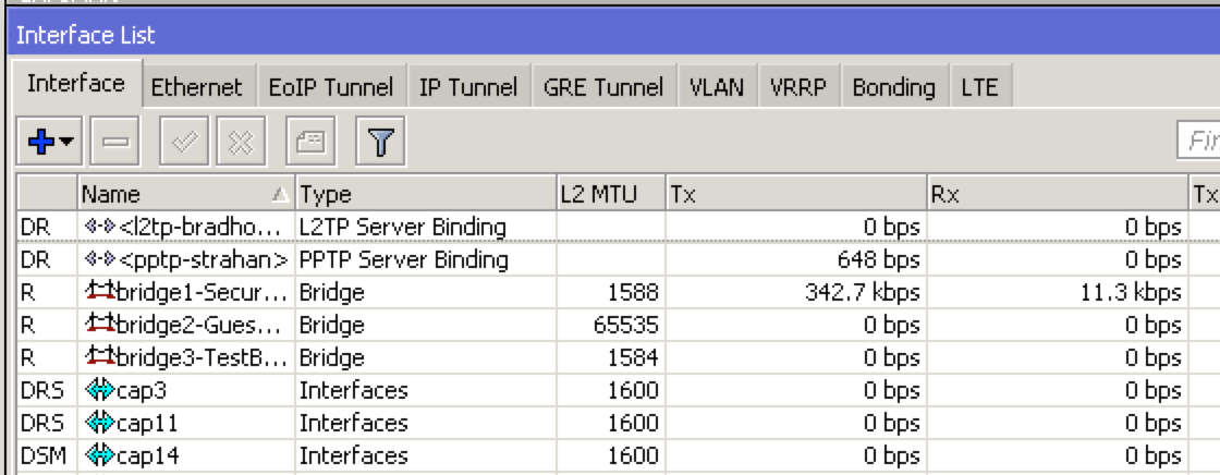
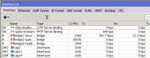
Here’s a screenshot from my router running CAPsMAN.  As you can see the CAPs are just interfaces!  Address them, run HotSpot on them, whatever you would normally do with a physical interface.

Screen Shot 2014-12-02 at 9.08.05 PM

The more I learn, the more I like and I am sure if you give CAPsMAN a try you will like it too!

I used Uldis’ presentation from the MikroTIk USA MUM 2014 to create this how to and he included a lot more detail.  You can ready his presentation HERE.

The manual for CAPsMAN is HERE.


RF Elements Simper Radio Antennas

In a surprise announcement yesterday at the WISPA Wispalooza in Las Vegas, RF Elements, one of my favorite manufacturers made a game changing announcement about their new product line, the RF Elements Simper.  The name is a shortened version of “Simply Perfect Radio” and is a bit hard for me to say, but the idea is fantastic.  Again, not yet a huge fan of the name, sorry JT.  I think it will grow on me though.

A picture is worth a thousand words, so here are a few, then we will discuss. Click on each to enlarge.

RFElementsSimper1 RFElementsSimper2 RFElementsSimper3 RFElementsSimper4


In summary, this is a new product line that centers around the top three WISP radios on the market: MikroTik, Ubiquiti and Cambium.  The premise of the system is that we standardize the RF connection between the radio and the antenna by using a new design that eliminates coaxial cables and replaces them with a no-loss waveguide, just like the licensed links have always used.  With a single twist lock mount, we can create numerous antenna designs that will work with any manufacturer’s radio for which we have a suitable enclosure or adapter.  It’s simplicity mated with maximum performance and reduced loss.  Like everything RFE does, the cases will be molded, ergonomic, clean, waterproof and thoughtfully designed.

Here are some of the many features they are touting:

NO LOSS

The connection with antennas via original TwistPort connector is virtually lossless.

Scalable

Simper is highly scalable concept of simplistic radios combined with wide range of antennas.

Easy

Deployment of Simper radio is a simple “twist and snap” to an antenna.

Multiplatform

Simper comes in multiple models running different OS. No need to migrate to new wireless platform.

Simple

Simper is compact and essentially simple product delivering the best wireless performance.

Cost Effective

Simper is the best cost performing wireless networking product today.

The New Approach

Simper unveils new concept of highly scalable wireless equipment.
Simper is the perfect match to growing requirements on performance, versatility and cost effectivity.

TwistPort Connector

Simper radios feature TwistPort Connector, our original quick-locking waveguide port. Connection and disconnection is brilliantly simple and can be done with one hand. TwistPort is the key feature to Simper scalability and performance.

NO LOSS

TwistPort Connector is virtually lossless. There are no traditional RF connectors or RF cables, that cause signal loss. TwistPort compatible antenna products include Symmetrical Sectors and UltraDish TP Antennas.

EASY DEPLOYMENT

When Using TwistPort Connector, deployment of Simper radio is a simple “twist and snap” to an antenna.

Simper Radio Adaptors

Simper Radio Adaptor make traditional connectorized radios compatible with TwistLock. Integration is simple, intuitive and requires no tools.
Adaptors will mate with most popular connectorized radios as UBNT Rocket M5, UBNT Rocket 5ac and Cambium Networks ePMP1000 connectorized radios.

What is Symmetrical Sector?

Symmetrical Sector antennas have symmetrical beam pattern in both horizontal and vertical panes.
The beam pattern does not vary with frequency, and antenna gain is balanced over wide frequency range.
Symmetrical Horn antennas are low loss and have attenuated side radiation lobes. These features make them excellent for use as Sector antennas.

SYMMETRICAL SECTOR BENEFITS

MORE COVERAGE

Symmetrical Sectors cover more area than traditional Sectors with narrow vertical beamwidth.

NO NULL

Symmetrical Sectors have no issues with connecting close clients.

EASY CO-LOCATION

As a result of very low sidelobes of horn antennas, Symmetrical Sectors are ideal for cluster deployments and co-location.

TWISTPORT CONNECTOR

Connecting Simper Radios to Sector Antennas is a simple “twist and snap”.

COMPACT SIZE

Symmetrical Sector antennas are compact and easy to mount virtually anywhere

WEATHERPROOF

Made of the best weather resistant materials as aluminium, plastic and st. steel.

That’s a lot of benefits and features and you can read more HERE.  We have already placed our stocking order as a RF Elements Master Distributor and I will notify you when they are here.  Get ready, I promise this innovation will change the  WISP game.