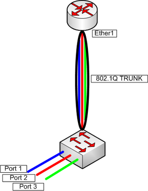
Router-On-A-Stick is a phrase referring to the connection of a 802.1Q capable switch to a single router interface. By trunking across the Ethernet interface and assigning separate Vlans to each of the switch’s ports or groups of ports, it is possible to create a configuration that simulates a router with many separate physical Ethernet interfaces. Consider the following example:
In this example, a router with a single Ethernet interface is trunked to a MikroTik switch. In practice, this same configuration can be used between two switches or two routers. The purpose of this article is to show the steps required to setup the MikroTik RB250GS switch as a trunked switch in the router-on-a-stick configuration.
To log into the RB250GS switch, simply web browse to 1 92.168.88.1 from a computer on the same phyical network segment with an IP on the same subnet, 192.168.88.0/24. The default user name is admin with no password.
All settings may be left at the defaults with the exception of a few.
In this example we are using Vlan Id’s 1, 200, 300 and 400. Note that the switch will respond to http requests to its IP address on all ports. This behavior is a bit different than Cisco IOS that responds to untagged traffic via an IP bound to Vlan 1. The way the OS is built, there is no need for a default gateway or a subnet mask.
Selection of the Vlan ID and the assignment to the ports is your choice, decide what Vlan ID’s you will use and where you will assign them.
In this example we need two ports for devices on Vlan 300 on Ports 3 & 5 and one port for device on Vlan 400 on Port 4 and one port for a device on Vlan 200 on port 2.
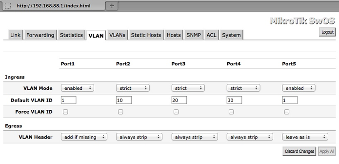
1. Begin by clicking on the VLAN tab and make the following changes, assuming the trunk port will be Port1 (the port that is connected to the router).
2. The VLAN page determines how the switch strips the Vlan tags with specific Vlan ID’s from the packets as they exit these ports. Setting Port 1 to Vlan Mode “enabled” and VLAN Header to “add if missing” makes Port 1 a trunk port.
3. When done, your VLAN page should look similar to this:
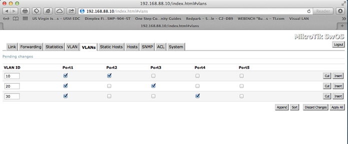
4. Next, click on the VLANs tab. This is where you create the Vlan Id’s to be used on the switch and on which ports these tags will be applied. So, for example, in this scenario, if I create a Vlan interface on the router with a Vlan ID of 200, that traffic will appear on the switch on ports 3 & 5.
5. Here is the example:
6. The last step is to change the IP address, system identity and the password on the System tab and configure the router.
The router configuration is a standard one for Vlans, create Vlan interfaces attached to the Ethernet interface that is connected to the switch (in this example Ether1) and match the Vlan ID numbers you assigned to the switch. Then bind your IP addresses to the Vlan interfaces and you will be set.
ISP Supplies sells the RB250GS, and it is a great bargain for the price point.


